Understanding Large Load Interconnection
An overview of the process that transmission providers and large load customers such as data centers use when a large load customer requests to connect to the electric grid.
When most homes connect to the electric grid, they do so through the electricity distribution system, the smaller wires that deliver electricity from substations to homes and businesses. However, larger loads — those exceeding approximately 20 megawatts (MW) such as data centers — require direct connection to the transmission system, which delivers electricity around the region at the substation level.
Before connecting a large load to the transmission system, grid operators evaluate the impact that the new load will have on the system and determine (1) whether existing transmission lines, substations, and related infrastructure can accommodate the additional demand without compromising system reliability or integrity, and (2) whether upgrades or new infrastructure are necessary. Assuming the customer is willing to pay their portion of identified costs, the relevant utilities then make the needed upgrades so that the large load can energize and draw power from the grid.
The load interconnection process does not:
- Assess whether there is sufficient generation capacity to serve the new load reliably. Typically, generation needs are addressed through markets (where markets exist) and/or integrated resource planning (IRPs).
- Set a large load customer’s electricity rates. While the large load interconnection process may identify up-front costs the large customer must pay, regulators set ongoing electricity costs through separate utility rate cases, tariffs, and transmission owner or regulatory-approved pricing structures. RMI has previously covered common provisions in utility tariffs and other considerations for integrating new large loads.
- Identify broader, system-wide transmission needs across the entire grid operator’s footprint. Planners conduct system-wide transmission planning processes separately, which we discuss in Article #3.
From request to power: How transmission upgrades are identified
While it varies across regions, large load interconnection generally follows similar procedures, timelines, and study processes. Typically, the large load customer first works with the local utility, and together they submit an interconnection request to the transmission owner. The transmission owner serves as the lead institution processing the request and coordinates closely with the Regional Transmission Organization (RTO), where one exists, throughout.[1]
For simplicity, we use “transmission provider” in this section to refer collectively to the transmission owner and the RTO, and “customer” to refer to the large load customer and the local utility. The graphic below summarizes the six conceptual steps in the load interconnection process. Variations across regions are detailed in the linked Appendix, and additional information on each step of the load interconnection process is available in a technical report by Elevate Energy and GridLab.

Step 1 — Preliminary Inquiry and Scoping: In the first step, the customer submits a formal request to connect a new load to the transmission provider, specifying the proposed location, size in megawatts, voltage level, and desired in-service date. The transmission provider then conducts preliminary scoping to assess the feasibility of the project and whether it can be served by the distribution grid. Typically, large loads over 20 MW connect at the transmission level to avoid inefficiencies or overloading distribution system capabilities.
Step 2 — Interconnection Request: If the project exceeds distribution system capabilities, the customer submits an interconnection request to the transmission provider. Some transmission providers require the customer to pay a study fee and/or provide more detailed project information.
Study sequence (Steps 3 through 5): At this stage, the request enters a series of three increasingly detailed studies conducted by the transmission provider to determine the needed transmission upgrades and costs.
One can think of the successive studies as similar to how one designs a new home.
- First, the feasibility study provides a rough cost and timeline for upgrades, just as a home developer conducts an analysis based on similar homes and approximate square footage.
- Second, the system impact study refines the initial estimate by designing more engineering details and their associated cost and timelines. In the home development process, this would be details such as the number of bathrooms, office space, and kitchen layout.
- Finally, the facilities study produces the technical blueprints that allow the builder to create a detailed project plan, purchase parts, and begin construction.
With each step of the process, the transmission provider delivers more detail and often requires additional customer financial commitment.
Step 3 — Feasibility Study: The feasibility study evaluates project viability using sound engineering judgment without performing a full interconnection or system impact analysis. After completing this study, the transmission provider gives the customer preliminary cost estimates and expected timelines. If the customer decides to proceed to the next phase, they pay additional study fees.
Step 4 — System Impact Study (SIS): The SIS includes a detailed technical analysis of how the new load will affect the broader transmission system including:
- Identifying the specific upgrades required
- Assigning preliminary cost responsibility
- Defining both customer interconnection facilities and network upgrades (described in more detail below)
The SIS is the most critical step in the process because it determines what must be built and who is responsible for it.
Step 5 — Facilities Study: Based on the SIS, the Facilities Study creates a full engineering plan that:
- Designs the required upgrades with construction-level detail
- Develops detailed equipment specifications
- Provides more precise cost estimates and schedules
The Facilities Study provides the technical design necessary for construction.
Step 6 — Interconnection Agreement: Once the studies are complete, the customer must then decide whether to proceed by executing an interconnection agreement and, in many cases, posting significant financial security and/or deposits. This agreement establishes the technical requirements, construction responsibilities, and cost obligations for both the utility and the customer.
Construction and energization: After the interconnection agreement is executed, the project moves into detailed engineering, permitting, and construction. The utility coordinates construction of the required upgrades, while the customer develops its on-site electrical infrastructure. Final testing and commissioning occur before the load is energized. As with all construction, actual timelines depend on the scale of required improvements, regulatory approvals, supply chain constraints, and coordination with broader generation, transmission, and distribution planning.
The full large load interconnection process can take anywhere from several months to several years from initial request to full energization, making it one of the most significant schedule and cost determinants in large load project development.
Interconnection triggers two types of transmission upgrades
The System Impact Study evaluates a new large load’s impact on the transmission network and may identify the need for both customer interconnection facilities and network upgrades, which we describe in the illustrative electrical diagram below. Load customers typically pay for the entirety of customer interconnection facilities and may have to pay for network upgrades as well.
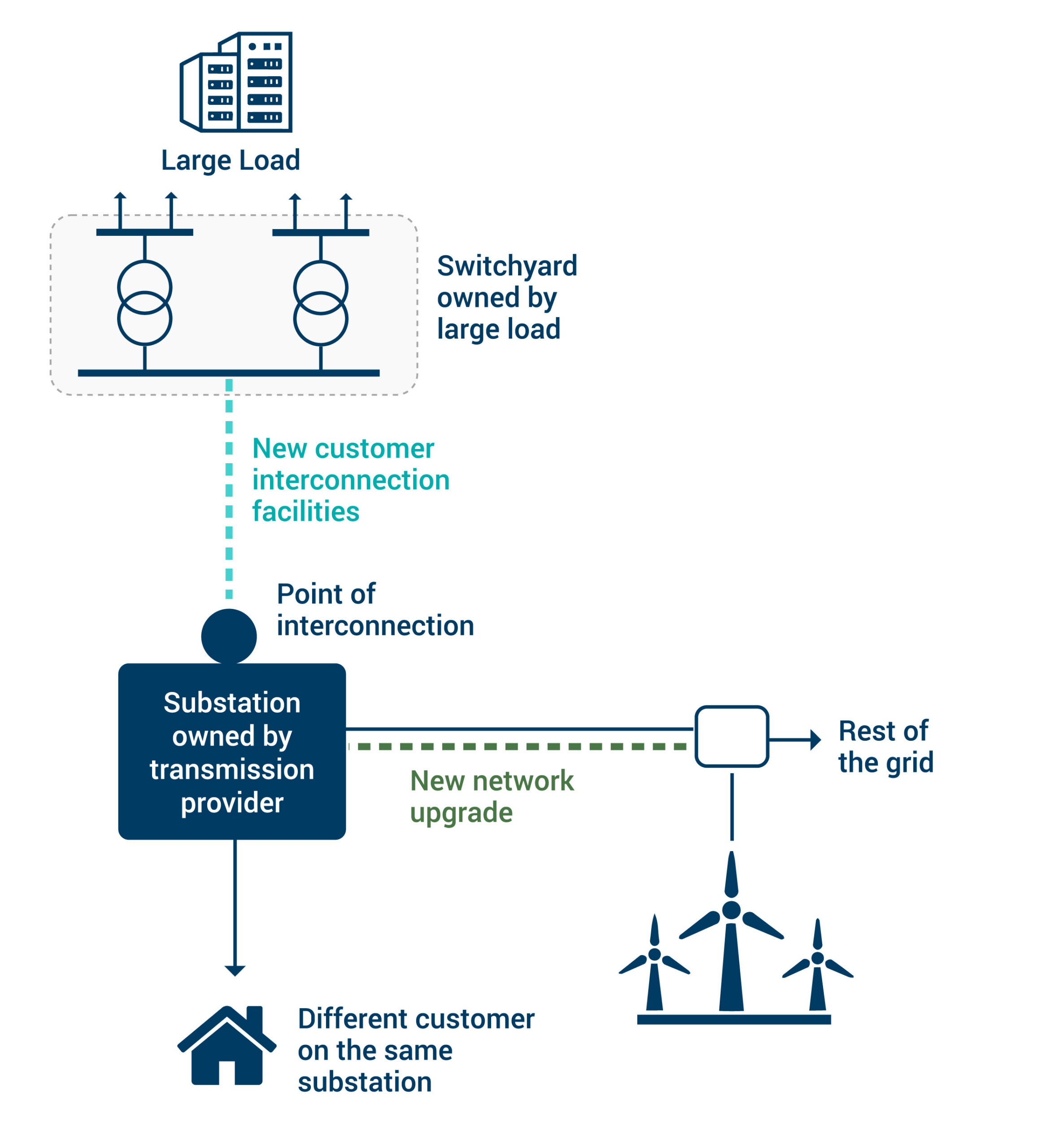
Customer interconnection facilities provide a direct connection between the load and the grid
The customer interconnection facilities establish a direct electrical connection between the new load and the substation where it connects to the rest of the electric grid, called the point of interconnection (POI). Customer interconnection facilities include substation bays, breakers, protection equipment, short tap lines, transformers, and in some cases reconductoring or new substations. The POI can be located within an existing substation or require an entirely new substation. In the graphic above, we indicate the customer interconnection facility as the light blue connection between the customer’s switchyard and the transmission provider’s substation.
Cost Implications: Because customer interconnection facilities are causally linked to the specific large load, their costs are typically allocated entirely to the large load customer. These costs can still be substantial, especially if the project requires constructing a new substation or the large load locates far from the nearest substation and requires a dedicated “radial” transmission line between the large load and the transmission substation.
Network upgrades ensure the broader transmission system can reliably serve the load
Network upgrades ensure the broader grid can reliably serve the addition of the new load at its POI. Network upgrades can include reconductoring existing lines, uprating transformers, adding reactive power support, or even constructing entirely new transmission lines or substations. Not all projects trigger needed network upgrades. In the graphic above, the new network upgrade is represented by the light green connection from two substations owned by the transmission provider.
The transmission provider identifies network upgrades during the SIS by evaluating power flows through their entire grid with the inclusion of the new load. Typically, the study starts with a system base case, which includes both existing transmission and transmission upgrades expected to come online soon. The transmission provider may then run power flow, stability, short-circuit, and electromagnetic transient (EMT) software simulations to understand how electricity will flow with the addition of the new load. Typically, they consider scenarios likely to cause issues including peak summer, peak winter, and light spring hours. In the United States, establishing a consistent set of modeling requirements is an active topic of research, with discussions led by Energy Systems Integration Group and the North American Electric Reliability Corporation (NERC).
Using the simulations, the transmission provider will determine if any applicable NERC standards were violated. If the transmission provider identifies violations, they will design network upgrades to mitigate the violations. On already-congested grids, these studies often identify network upgrades on portions of the grid far beyond the POI.
Cost Implications: Network upgrades are typically considered to benefit all customers of the transmission provider serving the large load, and costs are therefore allocated across the transmission provider’s service territory using methodologies from the Federal Energy Regulatory Commission (FERC). Once costs are assigned from the transmission provider to a local utility, then costs are allocated to retail customers using state-approved methodologies (see section below). In some cases, cost responsibility for network upgrades may be assigned to the new load customer or recovered through alternative methodology such as a pre-funding loan.
Large loads also drive system-wide transmission built to accommodate load growth more broadly
In addition to customer interconnection facilities and network upgrades, large loads in aggregate also drive system-wide transmission investments, which grid operators identify through system-wide planning. We describe system-wide planning further in Article #3. Note that in the top graphic, we do not include system-wide transmission investments, which lie beyond the diagram on the rest of the grid.
Cost Implications: System-wide transmission investments are designed to maximize system benefits to all ratepayers, so costs are allocated across the grid to all users using FERC-approved cost allocation methodologies. For more information on regional cost allocation, see this recent National Lab of the Rockies report.
Both federal and state regulators play roles in cost allocation and recovery
Once infrastructure investments have been identified, regulators play a critical role in approving transmission costs and determining how those costs are allocated. The division of responsibilities between federal and state regulators for transmission costs associated with large loads can be complex. The graphic below provides a high-level overview of federal and state regulatory roles, from transmission project design to cost allocation and recovery.

- Project identification and regional cost allocation: Transmission providers identify customer interconnection facilities, network upgrades, and system-wide transmission investments. Costs for network upgrades and system-wide transmission investments are then allocated to individual transmission owners using regional cost allocation methodologies approved by FERC.
- Approval for federal cost recovery: Once transmission owners are allocated their share of total costs, they file with FERC for annual approval to recover those costs using either stated rates or the FERC formula rate process. Transmission customers, such as local utilities, pay their share on a usage basis, typically measured in MW-month.
- State-level After federal cost recovery is approved and assigned to transmission users, the transmission user, commonly a local utility, proposes a rate design to allocate costs to its retail customer classes (e.g., residential, commercial, and industrial). State PUCs review and approve this design as part of retail ratemaking.
Large Load Tariff Dashboard
State regulators have a critical role in ensuring that transmission costs are fairly allocated across different customer classes. With a prudent cost allocation method established, PUCs can reduce risk to other customers by ensuring that large loads pay their expected share of costs via large load tariffs with robust ratepayer protections.
Are transmission upgrades from large loads driving grid inefficiency?
In this article, we describe the load interconnection process and how it identifies the need for both customer interconnection facilities, which only serve the interconnecting customer, and network upgrades that effect many grid users. In Article #2, we dive into how the rapid rise of large load interconnection request is fueling a surge in network upgrades — and why piecemeal network upgrades are likely an inefficient and costly way to build transmission that effects the entire system.
[1] RTOs or Independent System Operators (ISOs) exist in many, but not all, parts of the United States. US regions without RTOs/ISOs include the southeast and western United States (excluding California).